
Aircraft Fuel Injection Nozzles & Flow Dividers: How They Work and When to Replace Them
November 13th, 2026Posted by Cristhian Vera
Quick Facts on Aircraft Fuel Injection Nozzles & Flow Dividers
- In a continuous-flow fuel injection system, the fuel servo meters the fuel, the flow divider routes it to the individual injector lines, and a fuel injection nozzle at each cylinder discharges it into the induction airflow.
- The aircraft flow divider is also called a fuel manifold valve or fuel distributor. It is the distribution point between the servo’s single metered fuel outlet and the separate cylinder lines.
- Air bleed and continuous flow are not opposing nozzle types. Continuous flow describes the system; air bleed describes a nozzle feature, and continuous-flow systems can use air-bleed nozzles.
- A restricted nozzle can make one cylinder run leaner, but EGT or CHT trends and roughness do not prove a nozzle or flow divider fault. Ignition, induction leaks, valves, compression, and instrumentation can cause similar symptoms.
- Nozzle orifices and air-bleed holes are calibrated. Do not probe them with wire, drill bits, or picks unless the approved maintenance data permits it.
- A nozzle flow comparison can reveal a low-flow cylinder line, but the cause may still be the nozzle, injector line, flow divider outlet, or servo.
- There is no universal cleaning interval and no universal rule for replacing one nozzle versus the full set. Engine data, inspection findings, and the contamination source decide.
- Any replacement nozzle or flow divider, OEM or FAA-PMA, must be eligible for the exact engine and, for nozzles, the cylinder position.
This guide is published by AVStar Fuel Systems, a designer, manufacturer, and overhauler of FAA-PMA fuel injection servos, flow dividers, and fuel injection nozzles for general aviation piston engines. AVStar is a manufacturer, not a reseller. It builds its fuel systems in an AS9100-certified facility in Jupiter, Florida, holds more than 600 PMAs, validates its fuel systems on its proprietary Lambda Flow Bench before they leave the factory, and is a Lycoming Engines fuel system supplier.
Where Flow Dividers and Nozzles Fit in the Fuel-Injection System
In a typical continuous-flow fuel-injection system on a general aviation piston engine, fuel does not travel directly from the fuel servo to the individual cylinders. After metered fuel leaves the servo, it enters the flow divider. The flow divider routes that metered fuel into individual injector lines, and the injector lines carry it to a fuel injection nozzle at each cylinder.
The basic relationship is straightforward:
- The fuel servo meters the fuel.
- The flow divider distributes and routes the metered fuel.
- Injector lines carry the fuel to each cylinder.
- Fuel injection nozzles discharge the fuel into the induction airflow.
Each component performs a separate job, but engine operation depends on the entire system working together. A problem at one point in the system can produce symptoms that appear to originate somewhere else. An abnormal exhaust gas temperature, elevated or reduced cylinder head temperature, rough-running cylinder, power loss, rough idle, or fuel-flow discrepancy may point toward a nozzle or flow-divider concern, but those symptoms are not a diagnosis by themselves.
Ignition faults, induction leaks, valve issues, compression problems, fuel-servo discrepancies, incorrect mixture control, fuel-pressure conditions, injector-line restrictions, airflow differences, contamination, and other engine conditions can cause uneven cylinder-to-cylinder operation. For that reason, an A&P mechanic should approach suspected nozzle or flow-divider issues with a system-level diagnosis rather than replacing parts based solely on engine-monitor data or a pilot report.
What an Aircraft Flow Divider Does
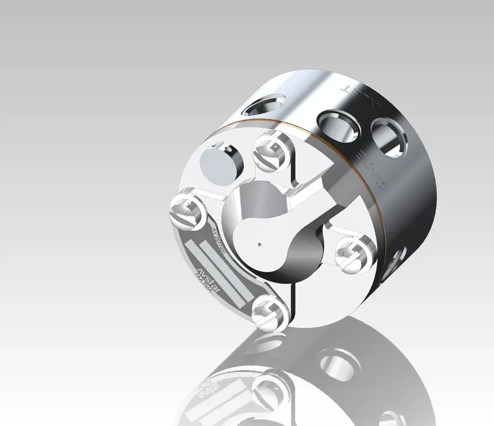
The aircraft flow divider, sometimes called a fuel distributor or fuel manifold valve, receives metered fuel from the fuel servo and distributes it to the individual cylinder injector lines. In a multi-cylinder continuous-flow fuel-injection system, it serves as the transition point between a single metered-fuel supply and the individual fuel lines that feed each cylinder.
The flow divider is normally mounted on or near the engine and includes an inlet connection from the fuel servo plus outlet ports that connect to the injector lines. Each outlet serves a specific cylinder. The injector lines then carry fuel from the flow divider to the nozzle assemblies installed in the cylinder heads or induction-system locations specified by the engine design.
The flow divider does more than serve as a passive manifold. In many continuous-flow systems, it includes an internal diaphragm, spring, valve, or poppet arrangement that influences when fuel is delivered to the individual injector lines. The design helps coordinate the start of fuel delivery to the cylinders as metered fuel pressure rises.
The specific construction and operating characteristics depend on the fuel-injection system and engine application. Mechanics should use the maintenance data for the exact installed system rather than assuming that all flow dividers operate identically.
An aircraft flow divider should not be confused with a fuel selector, transfer pump, fuel pressure regulator, or fuel servo. The selector controls which tank or fuel source is connected to the system. A transfer pump moves fuel between tanks or compartments. The servo meters fuel in response to airflow and mixture-control inputs. The flow divider distributes the fuel after it leaves the servo and before it reaches the individual injector lines and nozzles.
How a Flow Divider Works
At a practical level, the flow divider receives fuel that has already been metered by the fuel servo. As the servo delivers fuel, pressure in the divider rises. The internal components respond to that pressure and permit fuel to enter the individual outlet passages leading to the injector lines.
The purpose is to route the metered fuel to each cylinder through a controlled distribution point. The injector lines and nozzles then deliver that fuel to the appropriate cylinder’s induction airflow.
During normal operation, fuel flow through the system is continuous rather than timed by individual electronic injectors, as in many automotive systems. The fuel servo meters the quantity of fuel supplied in relation to airflow and mixture setting. The flow divider distributes the metered fuel among the individual cylinder lines. The nozzles discharge the fuel into the intake port or induction passage, where it mixes with incoming air before entering the cylinder.
The flow divider’s internal condition can affect the consistency of fuel delivery. Contamination, sticking internal components, leakage, diaphragm-related issues where applicable, damaged springs, incorrect assembly, worn parts, or restricted passages may affect operation. However, a flow-divider concern should be confirmed using applicable maintenance procedures. Engine roughness or an uneven EGT spread does not automatically establish that the divider is defective.
Because the divider is part of a calibrated fuel-metering and distribution system, unnecessary disassembly can create new problems. A mechanic should follow the component manufacturer’s instructions, engine manufacturer’s documentation, and applicable overhaul or bench-test guidance when evaluating or servicing a flow divider.
What an Aircraft Fuel Injection Nozzle Does
An aircraft fuel injection nozzle is the final fuel-delivery component in the continuous-flow injection path before fuel enters the cylinder’s induction airflow. Each nozzle receives fuel through its individual injector line and discharges fuel through a calibrated opening or openings into the intake port or induction passage.
The nozzle must provide the intended fuel discharge pattern and flow characteristics for the engine and fuel-injection system. Its location, orifice size, air-bleed arrangement, part number and installation orientation may be specific to the cylinder position and engine model.
Fuel injection nozzles are sometimes referred to as injectors, injector nozzles, fuel nozzles, or nozzle assemblies. Although terminology varies, the core function remains the same: deliver metered fuel into the induction airflow in a controlled manner.
The nozzle itself does not independently decide how much fuel the engine receives overall. The fuel servo meters the total fuel quantity, and the flow divider routes that metered fuel to the individual cylinders. However, restrictions or differences at a nozzle can affect how evenly the available fuel is distributed from cylinder to cylinder.
A partially restricted nozzle may cause one cylinder to receive less fuel than the others. Depending on the engine and operating condition, that cylinder may run relatively leaner and show a different EGT or CHT pattern. A nozzle with an abnormal discharge condition may also contribute to roughness, uneven idle, reduced smoothness during mixture adjustment, or an engine-monitor trend that differs from the other cylinders.
These indications should prompt inspection, but they should not be treated as proof that the nozzle is at fault. The injector line, flow divider, fuel servo, induction system, ignition system, valve train, cylinder condition, and instrumentation should all remain part of the diagnostic process.
How the Servo, Flow Divider, Injector Lines and Nozzles Work Together
Continuous-flow fuel injection is best understood as a sequence of connected functions.
The fuel servo meters fuel in response to engine airflow and mixture-control position. The flow divider receives the metered fuel and distributes it to individual outlet ports. Injector lines carry the fuel from those ports to the cylinder locations. The fuel injection nozzles discharge fuel into the induction airflow.
If any part of this sequence becomes restricted, contaminated, damaged, incorrectly installed, or misadjusted, the engine may not receive the intended fuel distribution.
A restriction before the servo can affect the overall quantity of fuel available to the system. A servo discrepancy can affect the total metered fuel delivered to the flow divider. A flow-divider problem can affect how fuel is routed into the individual lines. A damaged, restricted, or incorrectly routed injector line can affect one cylinder’s fuel supply. A contaminated or damaged nozzle can alter the discharge at an individual cylinder.
This relationship is important when troubleshooting uneven cylinder operation. A high EGT, low EGT, unusual CHT trend or rough-running cylinder may indicate a nozzle restriction, but a mechanic should not skip directly from an engine-monitor trend to a replacement nozzle. The symptom may arise from another part of the fuel system or from a non-fuel-related engine condition.
For example, a cylinder that appears to run hot may have reduced fuel delivery through a restricted nozzle. It may also have an induction leak, ignition timing issue, exhaust leak affecting the probe reading, cooling-airflow problem, internal cylinder condition, or inaccurate instrumentation. The correct response is to investigate the system methodically.
Air-Bleed Nozzle Operation
The terms “air bleed” and “continuous flow” are often treated as though they describe opposing nozzle types. They do not.
Continuous flow describes the overall fuel-injection system operating concept. In a continuous-flow system, metered fuel flows continuously from the servo through the flow divider, injector lines, and nozzles while the engine is operating.
Air bleed describes a feature that may be incorporated into a nozzle used within that continuous-flow system. An air-bleed nozzle uses air passages to help atomize and distribute the fuel charge as it enters the induction airflow. Fuel moving through the nozzle can draw air through one or more bleed passages, helping improve fuel atomization.
In other words, an aircraft can use air-bleed nozzles within a continuous-flow fuel-injection system. The two terms describe different aspects of the system rather than mutually exclusive alternatives.
The air-bleed holes and passages are small and can become obstructed by contamination, deposits, debris or improper cleaning practices. Because the holes are calibrated features, cleaning methods must follow approved maintenance instructions. Using wire, picks, drills, abrasive tools, or other sharp objects can damage or alter the nozzle passages. A nozzle that appears clean after aggressive mechanical probing may no longer have its intended flow or atomization characteristics.
When an air-bleed passage is blocked, the nozzle may not atomize fuel as intended. The resulting engine symptoms can vary by engine design, operating condition, and severity of the restriction. Proper evaluation requires the approved cleaning and inspection process for the installed nozzle assembly.
What Can Cause Injector Nozzle Restrictions
Fuel injection nozzles operate at the end of a long fuel path, so they can reveal contamination introduced upstream. A restricted nozzle may result from debris that entered the fuel system during servicing, maintenance, or component replacement. It may also result from contamination originating in the aircraft’s tanks, fuel lines, filters, strainers, selector component,s or engine fuel-injection system.
Possible sources of restriction include sediment, corrosion particles, deteriorated fuel hose material, tank sealant debris, water-related contamination, degraded seals, fuel-system deposits, metal particles, damaged filters, improperly serviced componen,ts or debris introduced when lines were opened.
Nozzle restrictions can also result from internal deposits that develop over time. Fuel quality, storage conditions, environmental exposure, long periods of inactivity, and operating conditions can contribute to deposits or contamination that affect small passages.
Improper maintenance practices can create a problem as well. Leaving injector lines open during service, failing to protect line ends from dust and debris, using inappropriate cleaning chemicals, using unapproved sealants, installing contaminated fittings, or reusing damaged seals can introduce contamination into the system.
Because a nozzle restriction may be only one part of a broader contamination issue, cleaning or replacing a single nozzle should not end the inspection. The mechanic should consider where the restriction originated and whether other components, including filters, strainers, fuel lines, the flow divider, or fuel servo, require evaluation. AVStar explains how upstream debris affects metering components and how servo contamination affects GA piston fuel systems.
Symptoms Associated With a Restricted or Contaminated Nozzle
A restricted or contaminated fuel injection nozzle can contribute to uneven fuel distribution and cylinder-to-cylinder operating differences. Potential symptoms include rough engine operation, uneven idle, roughness during mixture adjustment, reduced smoothness in cruise, hesitation, a cold or unusually hot cylinder trend, unusual EGT or CHT variation, abnormal fuel flow, reduced power, or cylinder-specific engine-monitor changes.
A partially restricted nozzle may reduce fuel flow to one cylinder. Under some conditions, this can make that cylinder operate relatively leaner than the others. The result may be a higher EGT trend, different CHT behavior, or roughness when the engine is operated near a mixture setting where small distribution differences become more noticeable.
However, an elevated EGT does not automatically mean a cylinder is too lean. EGT and CHT trends must be interpreted in the context of power setting, mixture position, cylinder condition, ignition timing, probe placement, instrument accuracy, induction-system condition, and the engine’s normal operating baseline.
Similarly, roughness does not automatically identify a contaminated nozzle. A fouled spark plug, magneto issue, ignition lead defect, valve problem, compression loss, induction leak, exhaust leak, fuel-servo issue, injector-line restriction, or other engine defect can create similar symptoms.
The mechanic should use the symptoms to guide inspection rather than allowing the symptoms to dictate the diagnosis.
Conditions That Can Affect Flow-Divider Operation
The flow divider can be affected by contamination, internal wear, corrosion, sticking components, seal deterioration, diaphragm-related defects where applicable, damaged springs, external leakage, incorrect installation, restricted outlet passages, or internal assembly issues.
A flow-divider problem may affect multiple cylinders or may create uneven delivery patterns that are not isolated to one nozzle. In some cases, symptoms may overlap with nozzle restrictions, injector-line problems, or fuel-servo discrepancies.
External fuel leakage around the divider, fittings, or injector-line connections requires immediate attention. Leakage can indicate damaged seals, loose fittings, cracked components, improper torque, installation problems, or internal issues affecting the assembly.
A flow divider may also require evaluation when fuel-distribution issues persist after nozzle and line checks have been completed, when multiple cylinders show unusual trends, when an approved flow test indicates a distribution concern, or when other diagnostic work points to a problem in the divider itself.
Bench evaluation may be appropriate when the installed system data, troubleshooting process, or component manufacturer’s instructions indicate that the divider requires a controlled inspection or test beyond what can be accomplished on the engine. A bench evaluation can help assess internal function, leakage, opening characteristics, and distribution performance, depending on the approved procedure and component type.
The flow divider should not be disassembled or adjusted casually. It is a precision fuel-system component, and service must follow applicable maintenance and overhaul data. If the required inspection or repair exceeds the scope of the maintenance being performed, the component may need to be sent to an appropriately qualified repair facility or manufacturer. AVStar offers both new and overhaul exchange flow dividers for applicable installations.
Causes of Uneven Cylinder-to-Cylinder Operation
Uneven cylinder operation can arise from fuel-distribution differences, but fuel distribution is only one possible cause.
A restricted nozzle, partially obstructed air-bleed passage, damaged injector line, or flow-divider discrepancy can affect the fuel supplied to one or more cylinders. A fuel-servo issue can affect total metered fuel and may contribute to broader mixture or fuel-flow concerns.
Ignition problems can create similar cylinder-specific symptoms. Fouled or worn spark plugs, damaged ignition leads, magneto timing discrepancies, weak ignition output, or intermittent electrical faults may produce roughness, temperature changes, and power loss that can be mistaken for fuel-distribution problems.
Induction-system leaks or airflow differences can also affect cylinder mixture. An intake leak can allow unmetered air into one cylinder’s induction path, creating a leaner condition without a fuel-nozzle restriction. Induction tubes, couplings, gaskets, clamps, and seals should be evaluated when the symptoms point toward a cylinder-specific mixture difference.
Mechanical engine conditions must also be considered. Valve leakage, worn guides, broken or weak valve springs, compression loss, cylinder damage, exhaust restrictions, cooling-airflow issues, and internal engine defects can alter cylinder temperatures and engine smoothness.
Instrumentation can mislead the troubleshooting process. An EGT probe may be damaged, improperly positioned, contaminated, or inaccurate. A CHT probe may produce a reading that does not reflect the cylinder’s actual temperature. Before making a major fuel-system decision based on a single cylinder indication, verify the data and compare it with other evidence.
The goal is not to dismiss nozzle concerns. It is to avoid treating an engine-monitor pattern as conclusive proof of a bad nozzle.
How A&Ps Inspect, Clean and Evaluate Nozzles
An A&P mechanic should inspect and service fuel injection nozzles according to the engine manufacturer’s maintenance documentation and the instructions applicable to the installed fuel-injection system. The proper method varies by nozzle design, engine model, and fuel-system manufacturer.
Inspection begins with the overall system condition. Before removing nozzles, review the reported symptoms, engine-monitor data, fuel-system history, recent maintenance, fuel quality, filter and strainer findings, ignition condition, and any known contamination concerns.
Injector lines should be inspected for chafing, cracks, wear, improper routing, damaged fittings, loose connections, and evidence of leakage. If lines are removed or disconnected, the open ends should be protected from dirt, dust, and other contamination. Introducing debris into an injector line during troubleshooting can create a new restriction or complicate the diagnosis.
When nozzle assemblies are removed, the mechanic should verify that the nozzles are correctly identified by cylinder location and part number. Some engine configurations use specific nozzles or calibrated variations in certain cylinder positions. Mixing components without confirming the approved configuration can affect fuel distribution.
Nozzle inspection may include checking the fuel-discharge orifice, air-bleed holes and vent lines in turbo applications, screens where applicable, nozzle body, threads, seals, O-rings and seating surfaces. The nozzle should be cleaned only with the solvents, methods and procedures approved for that system. Some manufacturer procedures specify particular cleaning fluids, soak periods, rinsing methods and compressed-air practices.
Sharp tools should not be inserted into calibrated discharge or air-bleed openings unless the applicable maintenance data specifically permits that method. Probing a nozzle with wire, a drill bit, pick, or similar tool can enlarge, scratch, or deform the passage. Even slight changes can affect fuel flow and atomization.
After cleaning, the mechanic should inspect the nozzle again for remaining debris, damaged passages, corrosion, cracks, worn threads, damaged seals, or other conditions requiring replacement. If a nozzle cannot be cleaned and restored in accordance with approved data, it should be replaced with the correct eligible part.
Testing Fuel Injection Nozzles for Proper Flow
A nozzle flow comparison can help identify meaningful differences in fuel delivery among individual cylinder nozzles and their associated lines. The exact procedure and acceptance criteria must follow the applicable aircraft, engine, or fuel-injection-system maintenance data.
In many approved or commonly used diagnostic approaches, the nozzles are removed from the cylinders while remaining connected to their individual fuel lines. Each nozzle is placed in a separate, clearly identified container corresponding to its cylinder location. The system is then operated using the approved method, so fuel output can be compared among the nozzles.
The purpose is to identify meaningful differences in output. A nozzle or line that delivers substantially less fuel than the others may be restricted. A line or nozzle that produces an unusual result may require further inspection. The nozzle should be identified carefully so that any discrepancy can be traced to the correct cylinder and line.
Fuel-system testing introduces fire and spill hazards. The aircraft must be secured, ignition sources controlled, appropriate containers used, and all applicable safety procedures followed. The mechanic should follow the approved procedure for the aircraft and fuel-injection system rather than using an improvised test setup.
A flow comparison can be valuable, but it does not always isolate the root cause. A low-flow result may originate in the nozzle, the injector line, the flow-divider outlet, the servo, or another part of the system. Further troubleshooting may be necessary before replacing components.
Cleaning Versus Replacement Considerations
Cleaning is appropriate when a nozzle has contamination or deposits that can be removed using the approved method, and the nozzle remains serviceable after inspection. Replacement is appropriate when a nozzle is damaged, corroded, worn, improperly modified, unable to be cleaned, out of approved limits, incorrectly identified, or otherwise unairworthy.
A nozzle should not be replaced merely because it appears discolored or because an engine-monitor trend seems unusual. Likewise, a nozzle should not be returned to service merely because it looks clean. The decision should be based on inspection findings, approved cleaning procedures, flow evaluation where applicable, and the maintenance data for the installed system.
The same principle applies to a flow divider. External leakage, internal malfunction, contamination, damaged fittings, or failure to meet applicable test requirements may require repair, overhaul, or replacement. But the divider should not be condemned before other likely causes of the symptom have been evaluated.
If debris is found in one nozzle, the mechanic should investigate the larger fuel system. A contaminated nozzle can be evidence of a restricted screen, deteriorated hose, contaminated tank, damaged filter, fuel-system corrosion, or debris introduced during maintenance. Replacing the nozzle without addressing the source can result in recurrence.
Should Individual Nozzles or a Complete Set Be Replaced?
Individual fuel injection nozzles can often be replaced when one nozzle is identified as damaged, restricted beyond acceptable cleaning, incorrectly configured, or otherwise unserviceable. The replacement nozzle must be the correct approved part for the specific cylinder location and engine configuration.
A complete set may be considered when multiple nozzles show contamination, damage, wear or inconsistent performance; when the engine manufacturer’s data calls for set-level replacement; when the source of contamination affected the entire system; or when a flow evaluation indicates a broader distribution issue.
There is no universal rule that every nozzle must be replaced whenever one nozzle is found to be defective. There is also no universal rule that individual replacement is always sufficient. The proper decision depends on the engine model, nozzle configuration, maintenance data, inspection results, contamination source, and overall system condition.
The mechanic should avoid mixing nozzle part numbers or calibrated nozzle types without confirming eligibility. Some engines use specific nozzle configurations at different cylinder locations. A nozzle that fits mechanically may not be approved for that position.
Selecting Replacement Nozzles and Flow Dividers
Selecting a replacement fuel injection nozzle or aircraft flow divider requires more than matching the appearance of the removed component. The replacement must be approved and eligible for the exact aircraft and engine installation.
Start with the applicable engine parts catalog, aircraft illustrated parts catalog, AVStar fuel system illustrated parts catalogs where AVStar components are installed, maintenance manual, fuel-injection system documentation, and part-number supersedure information. Confirm the exact part number, dash number, engine-model applicability, cylinder-position applicability, nozzle configuration, flow-divider configuration, and installation requirements.
For a nozzle assembly, verify the fuel-line connection, thread size, mounting arrangement, air-bleed configuration, required seals, orientation, cylinder applicability, and any calibration or part-number distinctions. For a flow divider, verify the inlet and outlet configuration, number of cylinder ports, mounting arrangement, line connections, fuel-system compatibility, and approved engine application.
If an FAA-PMA replacement is being considered, verify that the exact PMA part is eligible for the aircraft and engine installation. Confirm the PMA manufacturer, part number, approved replacement relationship, applicable model eligibility, documentation, installation limitations, and any instructions for continued airworthiness.
An FAA-PMA replacement component may be an appropriate option when it is approved for the intended installation and installed in accordance with applicable maintenance data. The PMA designation alone does not establish that a replacement nozzle or flow divider is correct for every engine that uses a similar-looking component.
Before installation, inspect the received part for correct markings, condition, configuration, packaging, and documentation. Use the specified seals, hardware, torque values, safety procedures, and leak-check methods. After installation, perform the operational and inspection steps required by the approved maintenance data.
Bottom Line
Fuel injection nozzles and flow dividers are precision components within a larger continuous-flow fuel-injection system. The servo meters the fuel, the flow divider routes it to the individual injector lines, and the nozzles discharge it into the induction airflow. A restriction or discrepancy at any point can affect engine operation, but cylinder temperature trends, roughness, or fuel-flow indications should be treated as diagnostic evidence rather than proof of a failed component. The most reliable maintenance approach is to evaluate the complete system, use approved cleaning and test procedures, identify the source of any contamination, and replace only components that are confirmed unserviceable or incorrect for the installation.
Get the Right Nozzles and Flow Divider for Your Engine
AVStar designs and manufactures FAA-PMA flow dividers, fuel injection nozzles such as the AV2524864-2 fuel injection nozzle, and fuel injection servo value kits. Buying direct from the manufacturer means you can confirm part number eligibility and configuration with the people who build the components.
Speak with a technical rep: call AVStar at 561-575-1560 or visit AVStar Product Support.
Shop direct from the manufacturer: browse AVStar flow dividers and fuel injection components at AVStarDirect.com.
Frequently Asked Questions
What does a flow divider do in an aircraft fuel injection system?
An aircraft flow divider receives metered fuel from the fuel servo and routes it to the individual injector lines serving each cylinder. It is the distribution point between the single metered-fuel outlet from the servo and the separate nozzle assemblies installed at the cylinders.
In a typical continuous-flow system, the flow divider works with internal components that control the start and distribution of fuel flow as fuel pressure rises. The injector lines then carry the distributed fuel to the nozzles, which discharge it into each cylinder’s induction airflow. AVStar Fuel Systems manufactures FAA-PMA flow dividers in both new and overhaul exchange versions for applicable installations.
What are the signs of a clogged or failing fuel injection nozzle?
Possible signs include rough engine operation, uneven idle, hesitation, loss of smoothness, cylinder-to-cylinder EGT or CHT variation, a cylinder that appears unusually hot or cold, abnormal fuel-flow behavior, or engine-monitor trends that differ from the established baseline.
These signs do not automatically confirm a clogged or failing nozzle. Ignition faults, induction leaks, injector-line restrictions, flow-divider discrepancies, fuel-servo issues, compression problems, valve defects, probe inaccuracies, and other engine conditions can cause similar symptoms. The nozzle should be inspected and tested as part of a complete diagnostic process.
How do you test aircraft fuel injection nozzles for proper flow?
The approved test method depends on the aircraft, engine, and installed fuel-injection system. A common diagnostic approach involves removing the nozzles from the cylinders while keeping them connected to their correctly identified injector lines, placing each nozzle in a separate container, and operating the system using the approved procedure to compare fuel output.
A significant flow difference may indicate a restriction or discrepancy, but further testing may be needed to determine whether the cause is the nozzle, the injector line, the flow-divider outlet, the fuel servo, or another part of the system. Fuel-system testing must be performed using the applicable maintenance data and appropriate fire-safety procedures. AVStar validates the fuel systems it produces on its proprietary Lambda Flow Bench before they leave the factory, but field testing on the aircraft should still follow the approved procedure for the installed system.
Is an uneven EGT spread always caused by a nozzle or flow divider?
No. An uneven EGT spread can come from a restricted or contaminated nozzle, a blocked air-bleed passage, a damaged or restricted injector line, a flow-divider problem or a fuel-servo discrepancy, but it can also come from conditions that have nothing to do with fuel distribution.
Spark-plug fouling, magneto timing, ignition-lead defects, induction leaks, valve problems, compression loss, cooling issues, exhaust leaks, and inaccurate EGT or CHT instrumentation can produce similar symptoms. A systematic diagnosis is necessary before assigning the cause to fuel distribution.
How often should fuel injection nozzles be cleaned or replaced?
There is no universal cleaning or replacement interval for all aircraft fuel injection nozzles. The required inspection and service intervals depend on the engine manufacturer, fuel-injection system, aircraft maintenance program, service instructions, operating environment, and the condition of the components.
Nozzles may be inspected or cleaned during scheduled maintenance, when troubleshooting roughness or uneven cylinder operation, after fuel contamination is discovered, or when required by applicable maintenance data. Replacement should be based on confirmed condition findings, approved limits, and manufacturer instructions rather than a generic time or hour interval.
What is the difference between air-bleed and continuous-flow fuel injection nozzles?
Air bleed and continuous flow describe different aspects of the fuel-injection system and are not necessarily opposing nozzle types.
Continuous flow describes the system operating principle: metered fuel flows continuously from the servo through the flow divider, injector lines, and nozzles while the engine is operating. Air bleed describes a nozzle feature that uses air passages to help atomize and distribute fuel as it enters the induction airflow.
A continuous-flow fuel-injection system can use air-bleed nozzles. The air-bleed passages are small and must be inspected and cleaned only using the approved procedures for the installed nozzle assembly.
Can you replace individual fuel nozzles, or should you replace the full set?
An individual nozzle can often be replaced when one nozzle is confirmed to be damaged, incorrectly configured, restricted beyond approved cleaning limits, or otherwise unserviceable. The replacement must be the correct approved part for the particular engine and cylinder position.
A complete set may be appropriate when multiple nozzles are contaminated, damaged, or inconsistent; when a system-wide contamination source has been identified; when the engine manufacturer requires it; or when inspection and flow evaluation show a broader distribution problem. The decision should be based on the specific engine, nozzle configuration, maintenance data, and inspection findings. When AVStar components are installed, use the AVStar illustrated parts catalog for that fuel system model to confirm the correct part numbers.
Is a fuel manifold valve the same as a flow divider?
Yes. Fuel manifold valve, fuel manifold, fuel distributor, and flow divider are different names for the same component in a continuous-flow fuel injection system. Lycoming documentation commonly uses fuel manifold, while many parts listings use flow divider. AVStar lists these parts as fuel manifold (flow divider), for example the AV2576526-1. Whatever the name, the component receives metered fuel from the servo and distributes it to the individual injector lines, and the replacement must match the approved part number and configuration for the engine.
Can you clean aircraft fuel injection nozzles with a wire or drill bit?
Not unless the applicable maintenance data specifically permits it. Nozzle discharge orifices and air-bleed holes are calibrated passages, and probing them with wire, a drill bit, a pick, or a similar tool can enlarge, scratch, or deform them. Even a small change can affect fuel flow and atomization. Clean nozzles only with the solvents, soak periods, and compressed air practices specified for the installed nozzle assembly, then inspect them again before reuse.
What should be checked if debris is found in a fuel injection nozzle?
Treat the debris as evidence of a wider problem. Inspect the remaining nozzles and injector lines, the flow divider, the fuel servo inlet screen, filters, strainers, hoses and tanks to find where the contamination originated. Review recent maintenance, since debris is often introduced when lines are opened. Replacing or cleaning only the affected nozzle without addressing the source can lead to a repeat restriction. AVStar’s guide on how servo contamination affects GA piston fuel systems explains how upstream debris can reach the metering components.
Can an FAA-PMA flow divider or nozzle replace an OEM part?
An FAA-PMA flow divider or fuel injection nozzle can be an appropriate replacement when the exact PMA part is approved and eligible for the engine installation and, for nozzles, the cylinder position. Verify the PMA manufacturer, part number, replacement relationship, model eligibility, documentation and any installation limitations before installation. The PMA designation alone does not make a part interchangeable with every similar-looking OEM component. AVStar Fuel Systems is an FAA-PMA manufacturer of fuel injection servos, flow dividers, and fuel injection nozzles, holds more than 600 PMAs, and is a Lycoming Engines fuel system supplier. To confirm eligibility for a specific engine, call an AVStar technical rep at 561-575-1560.